
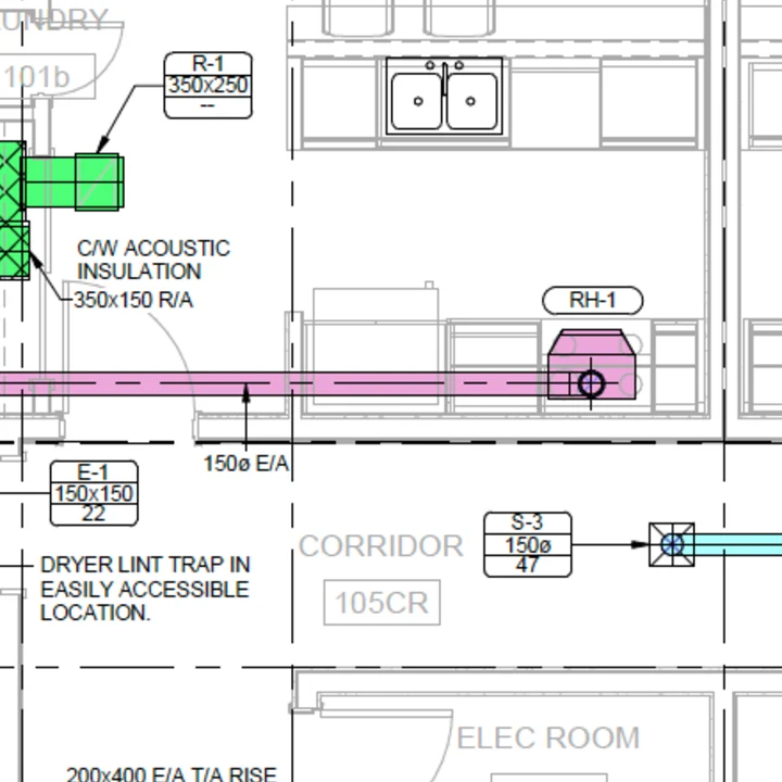
Mechanical drawings are the "M" sheets in a construction drawing set. They show the building's HVAC system: the equipment, where it goes, how air and water move between it, and how it is controlled. People call them HVAC drawings, mechanical drawings or blueprints interchangeably. To read them well, go in a set order: sheet index, legend and abbreviations, general notes, schedules, plans, roof plan, details and sections, controls, then the specifications.
Most people open the first floor plan and start counting. That is the slowest way to read a set, and the easiest way to miss things. This guide walks through the order experienced estimators use.
1. Start with the sheet index
The cover sheet or the first mechanical sheet usually lists every drawing in the set. Use it to answer three questions before you read anything else:
- How many mechanical sheets are there, and what does each one cover?
- Are there separate sheets for demolition, piping, or enlarged plans?
- Have any sheets been revised or added by addendum?
Sheet numbers often follow the National CAD Standard. The discipline letter comes first (M for mechanical), then a number that tells you the sheet type. In that system, 0-series sheets hold general information like legends, 1-series sheets are plans, 5-series sheets are details, and 6-series sheets hold schedules and diagrams. Not every engineer follows it, so confirm with the index.
2. Read the legend and abbreviations
Every engineer draws a little differently. The legend sheet decodes their HVAC symbols: supply diffusers, return grilles, thermostats, dampers, duct types and pipe types. Spend five minutes here and the plans will make sense much faster.
Common HVAC abbreviations you will see:
- RTU: rooftop unit
- AHU: air handling unit
- VAV: variable air volume (terminal unit)
- FCU: fan coil unit
- EF: exhaust fan
- ERV: energy recovery ventilator
- DOAS: dedicated outdoor air system
- UH / CUH: unit heater / cabinet unit heater
- SA / RA / EA / OA: supply / return / exhaust / outdoor air
- CFM: cubic feet per minute (airflow)
- MBH: thousand Btu per hour (capacity)
- ESP: external static pressure
- TYP: typical (repeat as shown)
- NIC: not in contract
- ETR: existing to remain
3. Read the general notes and sheet notes
General notes set the rules for the whole job. This is where you find statements like "all equipment shall be furnished with factory-mounted disconnects" or "contractor to verify existing units prior to bid." Sheet notes and keynotes, usually shown as numbered hexagons or circles on the plans, add instructions for specific spots.
Read them before counting. A single general note can add an accessory to every unit on the job.
4. Read the schedules before the plans
For estimators and distributors, the equipment schedules are the most important sheets in the set. Each schedule lists one type of equipment, with one row per tag. A typical schedule includes:
- Tag (RTU-1, EF-3, VAV-2-04)
- Manufacturer and model (the basis of design)
- Capacity (tons, MBH, CFM)
- Electrical data (voltage, phase, MCA, MOP)
- Weight
- Accessories and remarks
The schedule tells you what exists. It does not tell you how many. A schedule might list VAV-1 once, while the plans show it 40 times. Use the schedule as your checklist, then go to the plans to count.
Read the remarks column carefully. It is where engineers hide things like "provide with 14-inch roof curb," "factory-mounted smoke detector," or "see spec for hail guards."
5. Read the floor plans
Floor plans show where each piece of equipment and every air device sits. A few things to know:
- Ductwork is shown as double-line (drawn to scale with both sides of the duct) or single-line (one line with a size callout). Double-line is more common on larger jobs.
- Air devices usually carry a tag plus a CFM and neck size, like "A / 150 / 8".
- Equipment tags sit next to the unit, often inside a box, ellipse or hexagon.
- Enlarged plans show crowded areas (mechanical rooms, restrooms, kitchens) at a larger scale. Do not count the same item on both the floor plan and the enlarged plan.
- Typical notes like "typical of floors 2 through 6" mean one drawn floor stands in for several.
Always check the scale, and be careful with reduced or half-size prints. If you measure off a half-size print with a full-size scale, every length is wrong.
6. Read the roof plan
On low-rise commercial buildings, much of the major equipment lives on the roof: rooftop units, exhaust fans, condensing units, ERVs and roof hoods. The roof plan shows their locations, curb requirements, and sometimes clearances. Cross-check every roof tag against the schedules. Roof equipment is high value, so a missed RTU is an expensive mistake.
7. Read sections, details and diagrams
Details show how things are installed: roof curb details, VAV box piping, duct connections, and equipment supports. Sections cut through the building to show heights and vertical routing. Riser and flow diagrams show how air or water moves through the system.
For a takeoff, details matter because they often specify accessories that appear nowhere else, like isolation rails, vibration isolators, or seismic restraints.
8. Read the controls drawings
Controls sheets show sequences of operation, points lists and wiring diagrams. Even if controls are furnished by a separate contractor, check what is required at the equipment, such as factory-mounted controllers, BACnet communication cards or specific sensors.
9. Check the specifications
The HVAC specifications sit in Division 23 of the project manual. They list approved manufacturers, required performance, warranties and accessories. When the drawings and specs disagree, the contract documents usually say which one governs, but the safe move is to send an RFI or price the more expensive requirement.
Finally, check every addendum. Addenda can add units, change models, or delete scope.
Common mistakes when reading mechanical drawings
- Counting from the schedule instead of the plans
- Missing items marked as existing to remain, or pricing them when they should be excluded
- Double counting between floor plans and enlarged plans
- Forgetting to multiply typical floors
- Skipping the remarks column and general notes
- Working from an outdated set after an addendum
A faster way to read a set
On a 30-sheet drawing set, finding every schedule and counting every tag by hand takes hours. Monaro reads the set for you. It finds the equipment schedules, counts each tag across every sheet, and shows its work so you can check it. You still make the calls. You just stop doing the counting.
That is the whole idea behind automated HVAC takeoff software: the reading and counting is mechanical work, and the judgement is not.
Frequently asked questions
What are mechanical drawings? Mechanical drawings are the sheets in a construction set that show the HVAC system, and sometimes plumbing and fire protection. They are usually numbered with an M prefix.
What is the difference between mechanical drawings and HVAC blueprints? In everyday use, they mean the same thing. "Blueprints" is an older term for construction drawings in general.
What should I read first on a set of mechanical drawings? The sheet index, then the legend and abbreviations, then the equipment schedules. Read the plans after you know what you are looking for.
What does TYP mean on a mechanical drawing? TYP means typical. The item or condition repeats wherever the same situation occurs, so it must be counted more than once.
Where are HVAC specifications found? In Division 23 of the project manual, under the CSI MasterFormat system.
See it on your own set
Try Monaro free on your next drawing set. No credit card required.
